
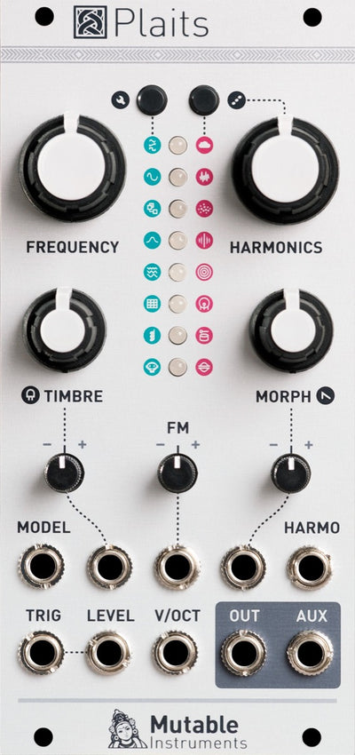
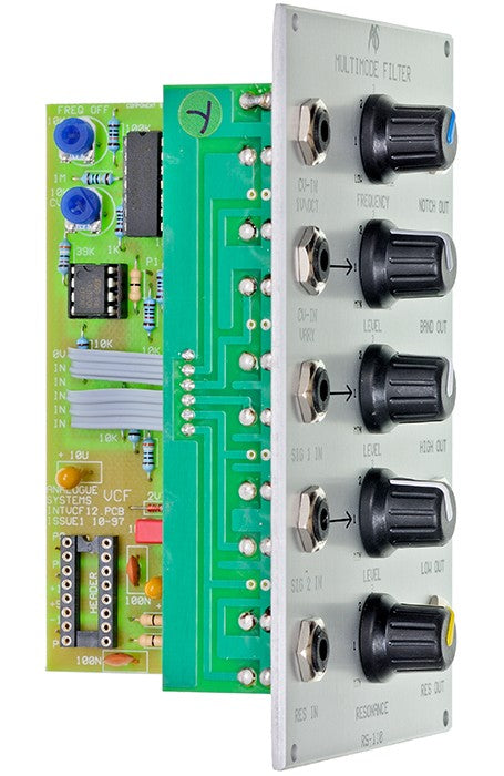
ANALOGUE SYSTEMS RS-110 DUAL BUS


The pioneers of synthesis understood that the flexibility with which a signal could be routed through filters was one of the most important elements of a synthesiser. Their modular synths featured four different types of filter: high pass filters which remove low frequencies (thus making a sound thinner), low pass filters (often used to emulate natural sounds) and band pass and band reject (notch) filters for resonant and special effects. These filters determined the power and the sound of the instrument.
In the early 1970s the Minimoog and the ARP Odyssey defined the architecture of integrated monosynths, and the rest of the synthesiser world was to follow their lead for more than a decade. The Minimoog provided just a single low-pass filter, while the Odyssey offered a simple high-pass filter in addition to its low-pass filter (but this was neither resonant nor voltage controlled). As a result, large modular synthesisers remained far more flexible than their smaller brethren.
This situation persisted until the 1990s when multimode filters reappeared on some of the newer digitally modelled synthesisers such as the Korg Prophecy. Unfortunately, and in common with all its brethren, the Prophecy is incapable of handling signals from the outside world. This is because the filter circuits do not exist: they are modelled mathematically, and form part of the complex calculations used to generate the analogue simulation. In contrast, the RS110 is a true analogue multimode filter. It is built from discrete components, and it eschews the use of the filter chips used by other manufacturers of analogue synthesisers. This means that the RS110 has a unique character that sets it apart from the crowd
IN USE
The RS110 consists of a two channel audio mixer followed by four, parallel, resonant filters with voltage controlled frequency and a unique "insert" point in the feedback path that generates and controls resonance.
Filter Modes
The RS110 offers four filter modes. These are 24dB/oct low-pass, 24dB/oct high-pass, 12dB/oct band-pass and 12dB/oct band reject (often called 'notch') filtering, with the cutoff frequencies (Fc) of the high-pass and low-pass outputs being the centre frequencies of the band-pass and notch outputs. Each of these filter characteristics is described in appendix 2.
There is no switch to select between the modes because all four are available simultaneously from the appropriate output sockets. However, the cut-off and resonance can not be defined individually for each, and the controls act upon each mode equally.
Cutoff Frequency
You can control the cut-off frequency manually using the FREQUENCY control. In its fully anticlockwise position, Fc is approximately 30Hz. As you rotate the knob clockwise Fc will increase until, it its fully clockwise position, it exceeds 15kHz. These extreme positions are called 'closed' and 'open' respectively. You may also control Fc using one or both of the CV inputs:
• CV-IN
If you apply a CV conforming to the 1V/oct standard, Fc will track the CV in exactly the same way as an RS90 VCO would if you applied the same CV to its CV-IN 1V/OCT socket. If the CV is supplied from a keyboard then, in common parlance, the filter is tracking the keyboard 100% and, with the resonance at maximum, you can 'play' the filter as if it were a conventional oscillator. You can also use this facility to make a notch or band-pass filter "track" the notes you are playing, and this can be used to create many special effects.
CV-IN VARY
You may wish Fc to track incoming CVs differently, so the CV-IN VARY input is provided. This socket and its associated LEVEL control allow you to specify the filter's sensitivity to CVs within the range ×V/oct to approximately 0.4V/oct. The former of these makes the filter invariant to incoming CVs, while the latter makes it over-sensitive compared to CV-IN.
You can determine Fc in the range 3Hz to 50kHz using combinations of the frequency control knob and the voltage control inputs.
Resonance
The filters have a common resonance, 'Q', that you can control using the RESONANCE knob. In its fully anticlockwise position, Q is approximately zero, and there is no emphasis of the signal at Fc. As you rotate the knob clockwise Q will increase, whereupon every mode of the RS110 will accentuate the harmonics that lie close to the cut-off frequency, Fc. Increasing Q further, the filters will exhibit ringing, and will severely colour any signals passed through them. Finally, if you continue to increase the resonance beyond a certain point, the filter will itself begin to oscillate, even in the absence of an input. Each mode will now produce a stable tone at the cutoff frequency determined by the various controls. This oscillation takes the form of (approximately) a sine wave, and it is produced by all four of the conventional audio outputs. The exact nature of the wave varies slightly from mode to mode, and you can use these subtle differences to create tonal variation when using the RS110 as an oscillator.
Feedback
Resonance is produced by feeding part of a filter’s output back into itself, thus creating a positive feedback loop. The RS110 provides an unique facility, allowing you to break this loop and insert signals of your own choosing.
RES OUT
The signal path normally fed back to the filter's input can be broken by inserting a lead at this point. The signal thus tapped may then be presented to any other input in the Integrator. The RESONANCE control then acts as a LEVEL control for the tapped signal.
RES IN
You may insert any signal here and it need not be derived from the RES OUT socket. Note, however, that taking a lead from RES OUT to RES IN does not replace the internal path because the internal circuit has a gain > 1.
Uses for RES OUT and RES IN include the introduction of voltage controlled resonance (achieved by routing the signal via an RS180 VCA) or the creation of special effects (achieved by modifying the signal using devices such as reverb units).
Signal Inputs and Outputs
The RS110 has two inputs: SIG 1 IN and SIG 2 IN, each with an associated LEVEL control. The inputs accept signals in the range ±10V, and these signals are mixed so that they can be filtered simultaneously.
The LEVEL controls offer unity gain in approximately the 2 o'clock position, marked '4' on the panel. At their fully anticlockwise position they attenuate the signal fully (MIN = -×dB gain) while at their fully clockwise position they offer a small gain. This (or, indeed, any high level signal) allows you to 'overdrive' the filter.
There are four outputs, one for each mode, and these each carry a signal in the range ±10v.
MISCELLANEOUS
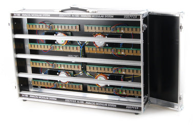
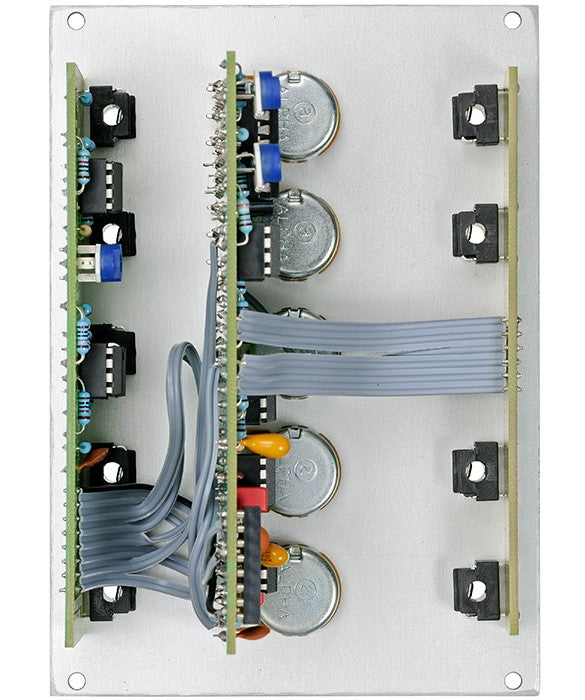
The Dual Bus version of the RS-110 features two power connectors, meaning it can be directly connected to either an Analog Systems or a Doepfer modular system. – Adapters are no longer necessary.
Because of the different position of the mounting holes there will be a gap of 0.5HP (= 2.5 mm) when mounting an Analogue Systems module next to a Eurorack module. Take this into consideration when planning your system. Gaps can be covered with 1.5HP wide blank panels by Doepfer.
DIMENSIONS
3U module in Analogue Systems form factor, 18HP wide, 65mm deep
power consumption: 45mA typical, 70mA when powering up


