The AJH Synth Sonic XV filter core is based on the diode ladder filter from the original Musonics Sonic V synthesiser dating back to the early 1970's. This particular diode ladder filter was originally developed by Eugene Zumchak (a former Moog employee) as a "work around" of the original patent (held by Dr Bob Moog) for the transistor ladder filter - the diode ladder was considered sufficiently different that it did not infringe the patent at the time. The diode ladder filter has quite a different character to it's transistor ladder parent, largely because the individual filter poles are not fully buffered as they are in the transistor ladder variant.
The diode ladder filter topology used in the Sonic V is rather different to the better known diode filters from EMS and Roland, as the frequency cutoff control voltage is actually summed with the audio signal before being added to the top of the dide ladder string. The early Roland and EMS diode ladders designs followed the more usual practice of feeding the frequency control voltage into the bottom of the diode ladder string.
It has a different character to the AJH MiniMod transistor ladder filter, sonically it is nearer to the Roland 303 and EMS Synthi A, but with it's own take on the diode ladder sound.
We have added many features which make the Sonic XV one of the most veratile Eurorack Modular filters currently available, and with the waveshaping features it can go way beyond traditional subtractive filtering.
Diode ladder filter
The original Sonic V Diode Ladder Filter core was a simple 24dB (four pole) low pass filter, we have added extra outputs so that the Sonic XV features additional 6dB (one pole) Low pass output and a Band Pass Output. Also,like other 24dB filters, due to phase cancellation the output level of the 24dB output would drop considerably as resonance was added - we have added a level correction circuit to the 24dB output that considerably reduces this effect and makes the filter rather more usable at higher resonance levels. We have also added external voltage contol of resonance with the RES-CV input.
The RES control manually regulates the amount of internal feedback applied to the filter core. At high levels of feedback (between positions 8 and 10) the filter will self-oscillate and produce a sinewave output without any audio input, however the filter will only self resonate at higher frequencies (2KHz and above) unless the Resonance Waveshaper is used, in which case the self resonant level can be extended down to around 150 Hz. When the resonance waveshaping is used the resonance waveform is no longer a sine wave, the exact waveform depends upon the various Resonance control settings.
If a control voltage is patched to the 1 V/Oct input when the filter is self resonating, the resonance wave can be played in the same manner as a VCO with a tracking range of 3 - 4 octaves. The CV scaling is not temperature corrected so it may drift with changes in ambient temperature. Please also note that the tracking scale changes if the Resonance Waveshaper is used, by default the scaling is calibrated for waveshaped Resonance.
Using the filter without waveshaping
The filter can be easily used without any waveshaping by simply rotating the IN MIX and RES MIX controls to zero (fully anticlockwise) In this configuration the Sonic XV filter performs as a regular resonant VCF, with 24dB Low pass, 6dB Low pass and Band Pass outputs.
Block diagram of Sonic XV Filter
The Sonic XV includes two waveshapers to add harmonics and distortion to both the pre filtered input signal and the resonance loop return signal. The illustration below gives a visual indication of how the various component parts of the Sonic XV filter are interconnected.
The audio signal path is shown in purple. An audio signal is patched into the Audio Input, and the signal level is attenuated by the IN Level control. Next is the IN MIX control, this determines how much of the input signal is routed to the Input Waveshaper (the "wet" signal) against being fed directly to the filter cor (the "dry" signal).
The Resonance loop is shown in Orange, and it can be seen that the RES MIX control determines how much of the "wet" signal from the Resonance Waveshaper is added to the "Dry" Resonance loop signal.

Input Waveshaper
The input waveshaper is a six stage diode alternate breakpoint wavefolder which is placed before the filter core. The output of this waveshaper can be mixed with the "dry" input signal in any amount from 0 to 100% using the IN MIX wet/dry blend control. The drive level of the wavefolder can be manually adjusted with the IN WAVE control, or by patching a control or modulation voltage into the IW-CV jack, it can be voltage controlled. There is also a three position bias control switch that allows additional variation to the input waveshaping.
The input waveshaper is most effective on waveforms with slower rise and fall times times, such as triangle waves and sine waves. It does also work with more complex waveforms and waveforms with fast rise and fall times, however the results may vary from subtle to interesting or even extreme depending upon the source waveform.
Due to the addition of this input wavefolder it is possible to use the Sonic XV to effectively "filter" sine waves patched to the input, as the wavefolder adds harmonic content to the input signal before it is processed by the filter core. Other signals with low harmonic content can be similarly "brightened up". This is certainly not possible with a regular low pass filter, in this case a regular VCF simple attenuates the level of a sine wave as the cutoff frequency is reduced, this is because a sine wave does not have any harmonic content, or it will make a signal with low harmonic content, such as a triangle wave, even duller.
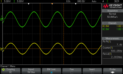
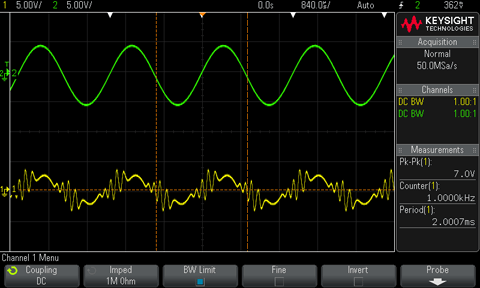
Some Input WaveShaper example waveforms:


Green trace is Input waveform, Yellow trace is the waveform from the 24dB Output. (Freq. Cutoff at 10, all resonance controls at zero)


Green trace is Input waveform, Yellow trace is the waveform from the 24dB Output. (Freq. Cutoff at 10, all resonance controls at zero)
Resonance waveshaper
The Resonance waveshaper is an overdrive waveshaper which is placed in the resonance loop of the filter, so obviously it is only effective when filter resonance is added to a sound. The output of this waveshaper can be mixed with the "dry" resonance loop signal in any amount from 0 to 100% using the RES MIX wet/dry blend control. The drive level of the wavefolder can be manually adjusted with the RES WAVE control, or by patching a control or modulation voltage into the R W-CV jack, it can be voltage controlled. .
Some Resonance WaveShaper example waveforms:
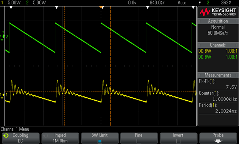

Sawtooth wave patched to filter input. Yellow trace shows the resonance without waveshaping (Left) and with Resonance waveshaping (Right)
Sawtooth wave patched to filter input. Yellow trace shows the resonance without waveshaping (Left) and with Resonance waveshaping (Right)
The above examples give an idea of some of the waveshaping that can be expected from the Input and Resonance Waveshapers. Obviously combinations of both can be used, and as much or as little waveshaping as desired can be used with a particular input signal by adjusting the IN MIX and RES MIX controls. So a small amount can be mixed in just to add a little fatness and warmth, or large amounts can be used to create some very aggressive sounds that can be manipulated with external voltage control.

Module Width: 14hp
Module Depth: 24mm (34mm with power cable)
Current Usage: 70mA Positive, 55mA Negative


