Frequency response curves
Frequency range is 20Hz ... 20kHz for all graphs
|
1. Output stages 12...1 mixed 50:50 with input signal (no feedback, no additional patches)
The first 12 frequency response curves show the behaviour of module when stages 1...12 are used as outputs for the final mixer (no feedback, no additional patching). This is the standard phaser application with a different number of phase shift stages. The frequency response curves of the higher stages show the typical comb filters of a phaser. The notches move through the audio spectrum as the manual phase shift control is operated or a control voltage is applied (for a standard phase shifter this is the triangle or sine wave from a LFO). The number of notches increase with the stage number: number of notches = integer of number of stages/2. Odd stage numbers lead to different behaviours in the higher and lower frequencies (low end: high pass behaviour, high end: passage). Even stage numbers show the same response in the higher and lower frequencies (passage for both). Stage 1 is nothing but a high pass filter, stage 2 a notch. |
 |
 |
 |
 |
 |
 |
| Stage 12 |
Stage 11 |
Stage 10 |
Stage 9 |
Stage 8 |
Stage 7 |
 |
 |
 |
 |
 |
 |
| Stage 6 |
Stage 5 |
Stage 4 |
Stage 3 |
Stage 2 (= notch) |
Stage 1 (= high pass) |
2. Inverted output stages 12...1 mixed 50:50 with input signal (no feedback, no additional patches)
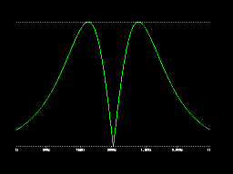
The second 12 frequency response curves show the behaviour if an inverter is inserted between the stage output in question and the final mixer (one of the polarizers can be used for this). The result is the inverse frequency response compared to the output without inverter: e.g. low pass for stage 1, band pass for stage 2. The resulting frequency response curve is simply obtained by vertical mirroring the first 12 curves. |
 |
 |
 |
 |
 |
 |
| Stage 12 |
Stage 11 |
Stage 10 |
Stage 9 |
Stage 8 |
Stage 7 |
 |
 |
 |
 |
 |
 |
| Stage 6 |
Stage 5 |
Stage 4
(the famous fast food filter known from A-107)
|
Stage 3 |
Stage 2 (= band pass) |
Stage 1 (= low pass) |
3. Output stages 12...1 mixed 50:50 with input signal with increasing feedback (the output stage is used for feedback to stage 1 too)
blue = min. feedback, red = medium feedback, green = high feedback
Additional feedback colors the sound. The third 12 frequency response curves show the behaviour of the filters with one feedback loop. Feedback comes from the stage used as output back to stage 1 (e.g. if stage 11 is used, feedback from stage 11 to stage 1).
|
 |
 |
 |
 |
 |
 |
| Stage 12, feedback from 12 to 1 |
Stage 11, feedback from 11 to 1 |
Stage 10, feedback from 10 to 1 |
Stage 9, feedback from 9 to 1 |
Stage 8, feedback from 8 to 1 |
Stage 7, feedback from 7 to 1 |
 |
 |
 |
 |
 |
 |
| Stage 6, feedback from 6 to 1 |
Stage 5, feedback from 5 to 1 |
Stage 4, feedback from 4 to 1 |
Stage 3, feedback from 3 to 1 |
Stage 2 , feedback from 2 to 1 |
Stage 1, feedback from 1 (out) to 1 (in) |
4. Output stage 12 mixed 50:50 with input signal with increasing feedback (feedback from stage 12...1 to 1)
blue = min. feedback, red = medium feedback, green = high feedback
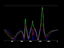
But it is not imperative to use the same stage for feedback and audio output. The fourth and fifth group of frequency response show the behaviour with different feedback loops. Always the same output is used (output 12 for group 4, resp. output 6 for group 5) but the feedback goes from stage 12, 11, 10, 9 ... and so on back to stage 1.
|
 |
 |
 |
 |
 |
 |
| Stage 12, feedback from 12 to 1 |
Stage 12, feedback from 11 to 1 |
Stage 12, feedback from 10 to 1 |
Stage 12, feedback from 9 to 1 |
Stage 12, feedback from 8 to 1 |
Stage 12, feedback from 7 to 1 |
 |
 |
 |
 |
 |
 |
| Stage 12, feedback from 6 to 1 |
Stage 12, feedback from 5 to 1 |
Stage 12, feedback from 4 to 1 |
Stage 12, feedback from 3 to 1 |
Stage 12 , feedback from 2 to 1 |
Stage 12, feedback from 1 (out) to 1 (in) |
5. Output stage 6 mixed 50:50 with input signal with increasing feedback (feedback from stage 12...1 to stage 1 for all filters)
blue = min. feedback, red = medium feedback, green = high feedback
|
 |
 |
 |
 |
 |
 |
| Stage 6, feedback from 12 to 1 |
Stage 12, feedback from 11 to 1 |
Stage 12, feedback from 10 to 1 |
Stage 12, feedback from 9 to 1 |
Stage 12, feedback from 8 to 1 |
Stage 12, feedback from 7 to 1 |
 |
 |
 |
 |
 |
 |
| Stage 12, feedback from 6 to 1 |
Stage 12, feedback from 5 to 1 |
Stage 12, feedback from 4 to 1 |
Stage 12, feedback from 3 to 1 |
Stage 12 , feedback from 2 to 1 |
Stage 12, feedback from 1 (out) to 1 (in) |
6. Output stages 12...1 mixed 50:50 with input signal with increasing feedback (feedback from stage 8 to stage 1 for all filters)
blue = min. feedback, red = medium feedback, green = high feedback
|
 |
 |
 |
 |
 |
 |
| Stage 12, feedback from 8 to 1 |
Stage 11, feedback from 8 to 1 |
Stage 10, feedback from 8 to 1 |
Stage 9, feedback from 8 to 1 |
Stage 8, feedback from 8 to 1 |
Stage 7, feedback from 8 to 1 |
 |
 |
 |
 |
 |
 |
| Stage 6, feedback from 8 to 1 |
Stage 5, feedback from 8 to 1 |
Stage 4, feedback from 8 to 1 |
Stage 3, feedback from 8 to 1 |
Stage 2, feedback from 8 to 1 |
Stage 1, feedback from 8 to 1 |
7. Some Examples with two feedback loops
blue = min. feedback, red = medium feedback, green = high feedback
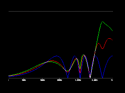
Last but not least the open structure of the module allows multiple feedback loops (e.g. stage 8 to 3 and stage 6 to 1) and even "forward" loops (e.g. from stage 5 to stage 9). In combination with polarizers additionally the feedback can be normal or inverted. This leads to a multitude of possible filter types. Some examples for multiple and forward loops are shown in the last section of the response curves.
|
 |
 |
 |
 |
 |
 |
Output: stage 10
feedback 1: 8 to 3
feedback 2: 6 to 1
Main peak moves from middle resonance (red) to high resonance (green) to new position
|
Output: stage 10 (inverted)
feedback 1: 6 to 1
feedback 2: 12 to 10 |
Output: stage 10
feedback 1: 6 to 1
feedback 2: 12 to 10 (inverted) |
Output: stage 10
feedback 1: 6 to 1
feedback 2: 12 to 10 |
Output: stage 10
feedback 1: 4 to 1
feedback 2: 10 to 1 (inverted) |
Output: stage 10
feedback 1: 2 to 1
feedback 2: 10 to 4 (inverted) |
 |
 |
 |
 |
 |
 |
Output: stage 10
feedback 1: 2 to 1
feedback 2: 10 to 3 |
Output: stage 6
feedback 1:9 to 1
feedback 2: 4 to 9 |
Output: stage 6 (inverted)
feedback 1: 9 to 1
feedback 2: 4 to 9 |
Output: stage 6
feedback 1: 9 to 1 (inverted)
feedback 2: 5 to 9 (inverted) |
Output: stage 6 (inverted)
feedback 1: 9 to 1 (inverted)
feedback 2: 5 to 9 (inverted) |
Output: stage 6 (inverted)
feedback 1: 5 to 1
feedback 2: 9 to 1 |
 |
 |
|
|
|
|
Output: stage 5
feedback 1: 8 to 1 (inverted)
feedback 2: 12 to 6 |
Output: stage 1 (inverted)
feedback 1: 8 to 1 (inverted)
feedback 2: 12 to 6 (inverted) |


