SYNTHESIS TECHNOLOGY E102 QUAD TEMPORAL SHIFTER


The Synthesis Technology E102 is a 4-tap delay for control voltages (a digital implementation of the Serge ASR – Analog Shift Register). There is also a digital noise generator with 8 different types of noise spectra. With no CV patched into the INPUT jack, the digital noise is sampled. Each clock pulse (internally set by RATE or patched into CLOCK IN) samples the INPUT and stores it as a 14-bit value. Successive clocks then shift the sampled voltage to the next output. The sampled voltage is shifted in the delay line as OUT1->OUT2->OUT3->OUT4. A quad 14-bit DAC drive the outputs accurate to <1mv.
A unique addition to the traditional ASR is the voltage-controlled DELAY. Selectable in 3 ranges, this adds delay stages in-between each output. For example, if DELAY was 2, then it would take 6 additional clocks for the OUT1 to ‘travel’ down the delay line to appear at OUT4. The INPUT is sampled every clock, not matter what the DELAY is. The outputs can be quantized to whole-note steps.
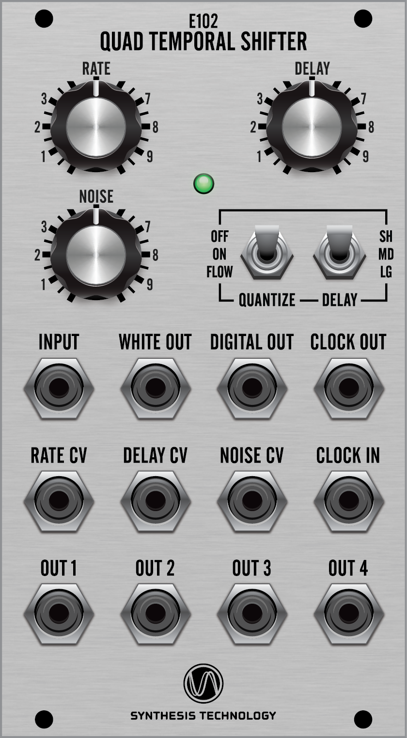
Controls and Jacks
RATE: sets the internal sample/shift clock rate from ~0.5Hz to 925Hz.
DELAY: sets the number of internal delay stages based on the DELAY switch position. NOISE: selects 1 of 8 different types of noise spectra. Karplus-Strong ‘pings’ to pink!
QUANTIZE switch: OFF will sample the input to the output. ON adds whole-step quantization each sample clock. FLOW will ignore the sample clock and not do any shifting. The INPUT is quantized and copied to all 4 OUTs. This is the ‘stand-alone’ quantizer mode. 1 whole step = 0.083V
DELAY switch. Sets the 3 DELAY ranges between the stages (not the total) as follows: SHORT: 1 – 8 (a ‘1’ means 1 clock between stages or a ‘zero’ delay)
MEDIUM: 1 -32 clocks
LONG: 1 – 511 clocks
INPUT: the CV to be sampled is patched into here. If no patch cord is inserted, the digital noise is sampled. The applied CV is sampled at the rising edge of the clock and appears at OUT1.
WHITE OUT: fixed spectra white noise output. Not effected by the NOISE pot or CV input. DIGITAL OUT: digital noise output.
CLOCK OUT: a 0 – 6.5V square wave at the same rate as the internal clock
The 3 CV input control jacks do not have associated attenuators. The input range is -5V to +5V, but it is important to note any applied CV is added to the matching panel control. Applied control CVs should be externally attenuated before patched into the E102.
CLOCK IN: any external LFO/VCO can over-ride the internal clock. For best results, use a pulse/square wave or a sine. The external clock must be at least 3V pk-pk. The upper frequency limit is 3KHz. Exceeding 3KHz may result in erratic behavior with loss of output voltage accuracy. Yes, it is possible to sample low-frequency audio, EGs or LFOs.
OUT1 – OUT4: the 4 CV outputs of the sampled INPUT. Each output can be thought of as a ‘tap’ in a delay line, that can vary from a length of 4 (1-stage DELAY, the minimum setting) to 1533 (3x511).
The most common use of the E102 is having each OUT drive a VCO. If you have a step sequencer, then use the sequencer’s clock into CLOCK IN and the sequencer’s CV out to INPUT. The 4 OUTs will then generate a musical canon (like “Row Row Row Your Boat”) when driving 4 VCOs. Each VCO will play the same note as the prior clocked output. This is of course assuming DELAY = 1. DELAY is not the same as a ‘clock divider’: When DELAY is not 1 (say it is 12), then every sample clock, the INPUT is fed into the delay. In this case there are 12 clock-delay stages between each out. If 0.25V was sampled and appears at OUT1, then 12 clocks later that same 0.25V appears at OUT2. There is no delay from INPUT to OUT1. The delays are OUT1 to OUT2, OUT2 to OUT3 and OUT3 to OUT4. Like this: INPUT>OUT1>Delay>OUT2>Delay>OUT3>Delay>OUT4. OUT1 is a ‘traditional’ Sample/Hold.
General Info
INPUT CV (the voltage being sampled and shifted): -6V to +6V.
Control CV Inputs: -5V to +5V, DC to 1KHz.
OUT1 – OUT4 range: -6V to +6V, +-1mv accuracy.
WHITE and DIGITAL NOISE output: -5V to +5V maximum.
Power supply range: +-9V to +-15V. Current (typical): -12V @20ma +12V @ 50ma
Factory scale trimmer: This is a factory calibration. A 1.000V input is adjusted for 1.000V at OUT1 (quantize OFF).


