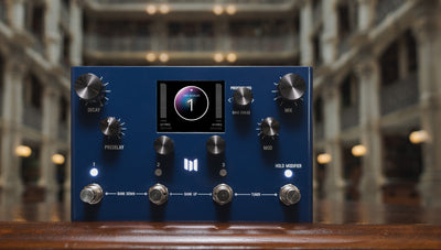
Clocked Delay Programs for Z-DSP
This collection of programs uses an external clock source to set the delay times for easy
synchronization. The delay programs include mono and dual delay lines for a variety of
classic effects.
Quick Start with Trigger Riot or Circadian Rhythms:
Note: the Clock control knob has to be set to 0 (full counter clockwise) in order for
tracking to work!
Trigger Riot:
The Clock output from the Trigger Riot cannot be used with these programs, so
connect output 1 to the VC-P2 CV input on the Z-DSP.
Start with a blank Preset, set the BPM to 120BPM, and start by adjusting the Pulse
Width on all division knobs to between 25 and 50%. You can save that into a preset
as a template you can easily recall later. Switch back to Divide and set a division of
4 on one output for the quarter note clock into the Z-DSP.
In the range of 60 to 180 BPM, divisions from 3 to 7 can be used if the Speed setting
is 16ths (the default). Above 120 BPM, a division of 8 will provide much longer
times which is particularly useful on the Dual programs.
Adjusting the pulse width to 50% on shorter divisions may also work for slower
tempos.
Circadian Rhythms:
The Clock output from the Circadian Rhythms cannot be used with these programs,
so connect output of channel 1 to the VC-P2 CV input on the Z-DSP.
Use consistent 4th note intervals on the CR for the best sync. The output needs to
be a GATE with at least 2 steps length for the Z-DSP to track.
Try a Gate on steps 1+2 (hold steps 1 and 2 until they turn Red) and 5+6 to send
4th notes. Above 120bpm, just a gate on steps 1 and 2 (half note) will give longer
delay times, particularly useful on the Dual programs.
How To Sync With A Clock:
The middle CV input is used for the Clock signal, and accepts clocks in the general ranges:
BPM Notes Pulse Width
Below 60 8th, 16th 50%
61-120 4th 25-50%
120-180 4th, half 25%
180+ half, whole 25%
Note: the Clock control knob has to be set to 0 (full counter clockwise) in order for tracking
to work!
When using regular intervals as the clock source in the ranges outlined above, these delay
programs will sync after a few clocks are input, and can track changes in Tempo provided
they stay in range.
A suitable pulse width length is needed for the programs to track the rising and falling edges.
In general, triggers are too short and pulse width duty cycles of 25-50% work well. The
16th note (4 PPQN) and DIN/MIDI (24 PPQN) clocks common to Euro have too short of
a pulse for the Z-DSP to track. Using a clock divider down to the note lengths above are
needed (Divide by 4 for 16th, 24 for DIN/MIDI). Clock information for specific devices are
listed in the ‘Device Compatibility’ section of this manual.
A Division control sets the ratio of the feedback time to the external clock length. Ratios
vary between programs, and include ratios of 1:1, 1:2, 1:3, 1:4 and 1:6 to easily set 8th, 16th
and triplet intervals.
Some of the programs have internal feedback while others will need the external Analog
Feedback path for repeats.
Algorithm Structure:
MONO:
Mono programs use a single delay line up to 1000ms in length. Left and Right inputs are
summed into mono and written into the delay line. Separate Left and Right output taps
feed their respective signal outputs.
Note that feedback, internal or external, also sums back into mono so both of the taps are
fed with each other’s signal. Using external feedback can allow for adjusting the amount
of feedback each tap uses and the outputs can be fed through different external processes
like filters and distortion.
DUAL:
Dual programs use two independent delay lines that are fed from Left or Right inputs. The
length of these delay lines is limited to 500ms. External feedback will only affect the same
Left/Right channel. The Ratios for Dual programs are 0.5 and below because the Tempo
calculation is based on 1000ms.
Note: Program 6 Stereo Ping Pong has two delay lines like a Dual program, but the input is
summed mono.
1> Mono L/R Clocked Taps
Single 1000ms delay line with inputs summed into mono and separate taps out to Left
and Right. Feedback is done through the external Analog Feedback.
DivL - Division for the Left tap. 6 ratios
Clock - Clock input (set at 0)
DivR - Division for the Right tap. 6 ratios.
Ratios (from 0-100% on knob):
Left Right
1:3 0.333 1:6 0.1667
3:8 0.375 3:16 0.1875
1:2 0.5 1:4 0.25
2:3 0.6667 1:3 0.3333
3:4 0.75 3:8 0.375
1:1 1.0 1:1 1.0
2> Mono Clocked Low Pass
Mono 1000ms delay line with summed inputs and separate taps out to Left and Right.
A Low Pass Filter is in the feedback path and the cutoff lowers as feedback increases.
Divide - Division for both Left and Right.
Clock - Clock input (set at 0)
Fdb+LP - Low pass filter cutoff and feedback level
Ratios (from 0-100% on knob):
Left Right
1:2 0.5 1:4 0.25
1:2 0.5 3:8 0.375
2:3 0.6667 1:3 0.3333
3:4 0.75 1:2 0.5
1:1 1.0 3:8 0.375
1:1 1.0 1:2 0.5
1:1 1.0 2:3 0.6667
1:1 1.0 3:4 0.75
3> Mono Clocked Fdbk+HPF
Mono 1000ms delay line with summed inputs and separate taps out to Left and Right.
A High Pass Filter is on the input and the cutoff rises with the feedback amount.
Note that the repeats can be very long on this program.
Divide - Division for both Left and Right.
Clock - Clock input (set at 0)
Fbk+HP - High pass filter cutoff and feedback.
Ratios (from 0-100% on knob):
Left Right
1:2 0.5 1:4 0.25
1:2 0.5 3:8 0.375
2:3 0.6667 1:3 0.3333
3:4 0.75 1:2 0.5
1:1 1.0 3:8 0.375
1:1 1.0 1:2 0.5
1:1 1.0 2:3 0.6667
1:1 1.0 3:4 0.75
4> Mono Clocked Bandpass
Summed inputs into a Mono delay line. Two separate taps feed Left and Right outputs.
Feedback runs through a one pole bandpass filter with fixed frequency but increasing Q
so the bandwidth narrows as the feedback increases.
Divide - Division for both Left and Right.
Clock - Clock input (set at 0)
Fb+Q - Feedback amount and increasing Q
Ratios (from 0-100% on knob):
Left Right
1:2 0.5 1:4 0.25
1:2 0.5 1:3 0.3333
2:3 0.6667 1:3 0.3333
3:4 0.75 3:8 0.375
1:1 1.0 2:3 0.6667
1:1 1.0 1:2 0.5
5> Dual Clocked Delays
Two 500ms delay line with inputs for Left and Right and separate out to Left and Right.
Feedback is done through the external Analog Feedback.
DivL - Division for the Left tap
Clock - Clock input (set at 0)
DivR - Division for the Right tap
Ratios (from 0-100% on knob):
Left Right
1:6 0.1667 1:6 0.1667
3:16 0.1875 3:16 0.1875
1:4 0.25 1:4 0.25
1:3 0.3333 1:3 0.3333
3:8 0.375 3:8 0.375
1:2 0.5 1:2 0.5
6> Clocked Ping Pong
Summed mono input feeds the Left delay line and the output of the Left is the input of
the Right delay line. Each delay is 500ms in length and the internal feedback sends the
output of the Right delay back into the Left.
A low pass filter cutoff is lowered as the feedback increases.
Divide - Same ratio for both delay lines (1:2, 1:3, 1:4, 1:6)
Clock - Clock input (set at 0)
Fdbk - Feedback amount and LPF cutoff (inverse)
Ratios (from 0-100% on knob):
Left Right
1:4 0.25 1:4 0.25
1:3 0.3333 1:3 0.3333
3:8 0.375 3:8 0.375
1:2 0.5 1:2 0.5
7> Dual Clocked HPF
Two 500ms delay line with inputs for Left and Right and separate out to Left and Right. A
High Pass Filter is in the feedback path and the cutoff frequency rises with feedback level.
Divide - Division for both Left and Right.
Clock - Clock input (set at 0)
HPF - High pass filter cutoff
Ratios (from 0-100% on knob):
Left Right
1:3 0.3333 1:6 0.1667
1:2 0.5 1:6 0.1667
1:2 0.5 3:16 0.375
1:2 0.5 1:4 0.25
1:2 0.5 1:3 0.3333
1:2 0.5 3:8 0.375
8> Dual Clocked Feedback
Two 500ms delay line with inputs for Left and Right and separate out to Left and Right.
Feedback is internal and a low pass filter removes high end from the repeats as feedback
increases.
Divide - Division for both Left and Right
Clock - Clock input (set at 0)
Fdbk - Feedback amount + LPF cutoff
Ratios (from 0-100% on knob):
Left Right
1:3 0.3333 1:6 0.1667
1:2 0.5 1:6 0.1667
1:2 0.5 3:16 0.1875
1:2 0.5 1:4 0.25
1:2 0.5 1:3 0.3333
1:2 0.5 3:8 0.375
Left Right 1:3 0.3333 1:6 0.1667 1:2 0.5 1:6 0.1667 1:2 0.5 3:16 0.1875 1:2 0.5 1:4 0.25 1:2 0.5 1:3 0.3333 1:2 0.5 3:8 0.375


